

How to Manufacturer Compact Microchannel Flow plate
Microchannel flow plats (MCP) are in use for decades in space flight instruments as lightweight, fast electron multipliers. The latest compact micro channel flow plate technique combines the thin film layers with the glass substrate made of capillary arrays of hollow glass. This combination provides the secondary and resistive properties of electron emissive. You may choose glass properties, resistance, and gain, independently, with the help of this technique. You can buy large area microchannel flow plates at a moderate price. Secondary MgO and AI2O3 emission films provide sustainable high gain since the charge extraction is done from the microchannel flow plate.
Today, we will discuss the different manufacturing techniques of MCP. You will also learn about the essential information about the MCP.
An Introduction to Compact Micro Channel Flow Plate (MCP)
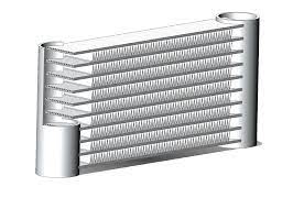
A compact micro channel flow plate is a planar, thin structure containing various parallel pores, small diameter oriented around the perpendicular. Ionizing pore walls is straightforward with incoming ions, energetic photons, or electrons. The secondary ionization electrons are below the pore with the electric field. Supplementary secondary electrons generate as they hit the wall until about 10000 cascades excludes from the pore’s bottom end. The development of an electric field is possible by applying the higher voltage between the MCP’s planner surface to another.
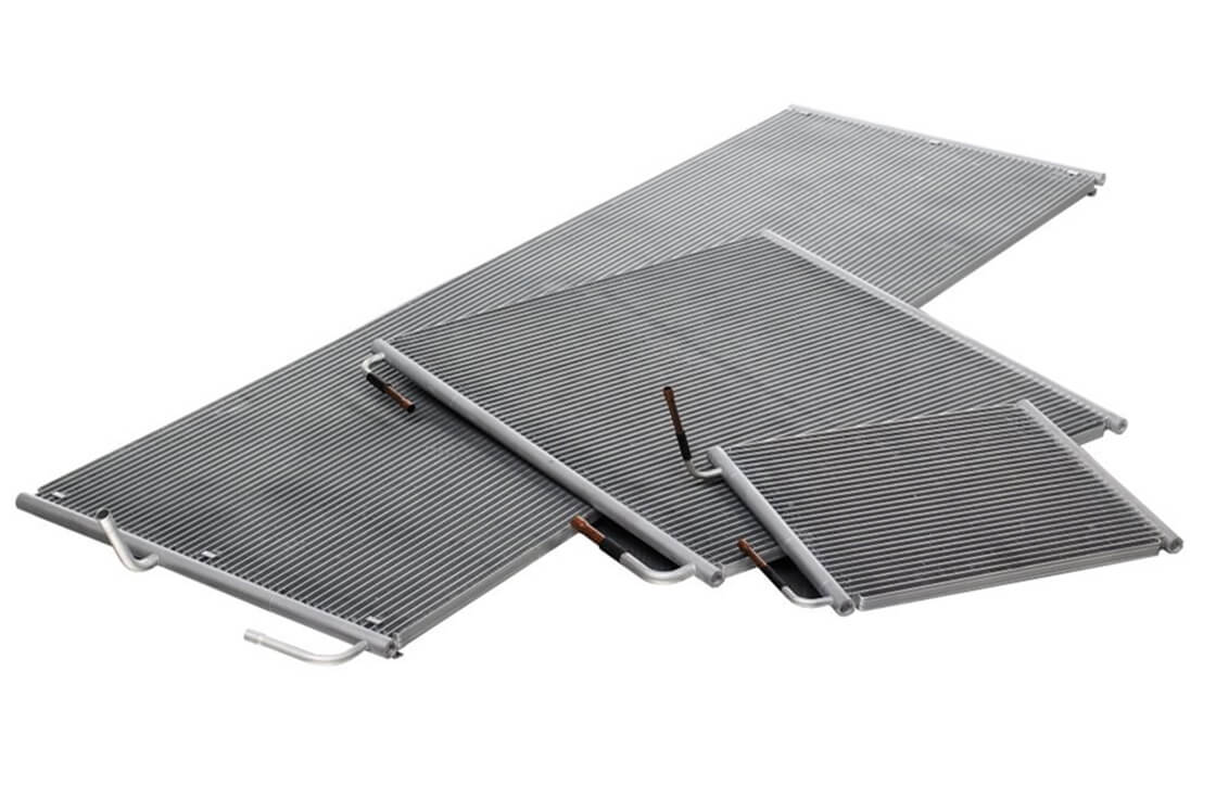
It is possible to stack two micro-channel flow plates for producing the electron gain of over million electrons. Microchannel flow plates consist of glass with 60% or even more ratio of open area to ensure less weight. Usually, the thickness is between 0.5mm to 1.5mm. The pore diameter of MCP can be between 2 µm to 150 µm or even more. The outlines of the surface area can have an arbitrary shape so that they can meet the needs of various detector configurations.
MCP Manufacturing Techniques
For over six decades, MCPs have been created using a single essential technique. However, a new technique has been introduced recently that combines the thin-film deposition method with glass-capillary array substrates to provide the essential secondary emissive and resistive MCP properties. This approach offers various advantages. It is possible to choose the emissive, resistive, and glass properties independently. You can make the glass robust mechanically and may choose to have a lower radioactive material content to reduce background activity. Now, let’s take a quick look at the two compact micro channel flow plate techniques for a better understanding.
1. Traditional Micro Channel Flow Plate Manufacturing Technique
In a traditional MCP manufacturing process, we fill lead-glass tubes (pipes) using glass rods. Assemblies of the rod and tube are codrawn thermally to help the tube (pipe) collapse near the rod for producing slender fibers using the lead-glass cladding and the inside core glass. Then, fibers are parallel-stacked and stretched together. After that, we fuse multiple assemblies of fiber together. Wafers cutting happen across fiber assemblies at a position where the plane is around the vertical fiber axis.
Then, core glass etching happens, leaving several pores, each usually around a diameter of 10 to 20 µm. After that, this lead-glass array gets the heat under hydrogen presence to reduce the glass surface chemically. Ultimately, we have the emissive and resistive surface which is ideal for electron amplification.
During its use, a traditional microchannel flow plate shows an initial gain reduction, usually followed by the sluggish decrease for the remaining lifetime of the MCP. Several studies are available on gain loss explanation. We will cover such studies in one of our next topics.
2. Atomic Layer Deposition Manufacturing Approach
ALD (Atomic-Layer-Deposition) is the latest compact micro channel flow plate manufacturing technique. It begins with drawn capillary tubes from the borosilicate glass similar to the conventional manufacturing of MCPs. However, these are hollow fibers, so we don’t need to cut away the core. This helps in manufacturing cost reduction and eliminated the upper limit, practically, on the diameter’s ratio length enforced by the process of etching. Then, the bundles of the fused capillary are sliced in a similar way as we see in the traditional process, for making flat adjacent pores plates. These are called GCAs (glass-capillary-arrays) and come with similar traditional lead-glass microchannel flow plate configuration after the etching of cores.
After completing the drawing of a glass capillary, the long capillaries’ parallel fusing into the water, block slicing happens for final polishing. We can see some quantity of water left from the process of cleaning in the channels. Microchannels get the hexagonal form, which turns more distinct in higher OAR (open-area-ratio), reedy wall capillaries. Around 74% of OARs are easy to achieve using this process. One of the most common examples of a hollow-drawn capillary application is lenses and X-ray concentrators.
Mechanical strength is essential for the acoustic launch environment and vibration for the spaceflight application. Traditional microchannel flow plates usually require substantial mechanical backing to deal with the vibration, which may limit the science performance. ALD coated microchannel flow plates have improved strength since it is possible to choose glass substrate independently for specific mechanical properties. Moreover, an ALD coated microchannel flow plate doesn’t need hydrogen firing, which avoids the embrittlement present in conventional MCPs because of the glass hydrogen diffusing.
Conversion of GCA into MCP
It is possible to convert GCA into a microchannel flow plate by adding the thin film for establishing the required plate resistance. You can then add another thin film to create a subordinate emission layer. ALD technique deposits the important thin film and the MCP application decides about the resistance to be chosen. Remember that high resistance will result in a low-power operation that is helpful for portable instruments or spaceflight.
Low-resistance is suitable for higher event rates. Emission layers can be MgO or Al2O3. The Al2O3 offers reliable durability and gains stability in the long term against air exposure. On the other hand, MgO offers a higher gain. Every single microchannel comes with a resistive coating through the process of ALD. This layer creates the strip current or DC through a compact micro channel flow plate that recharges channels.
Both traditional and ALD techniques are in use to manufacture a compact micro channel flow plate in this modern era. However, both come with unique benefits and downsides. You can contact us for further queries on this topic.
